Search
optics

Reflection-Reducing Imaging System for Machine Vision Applications
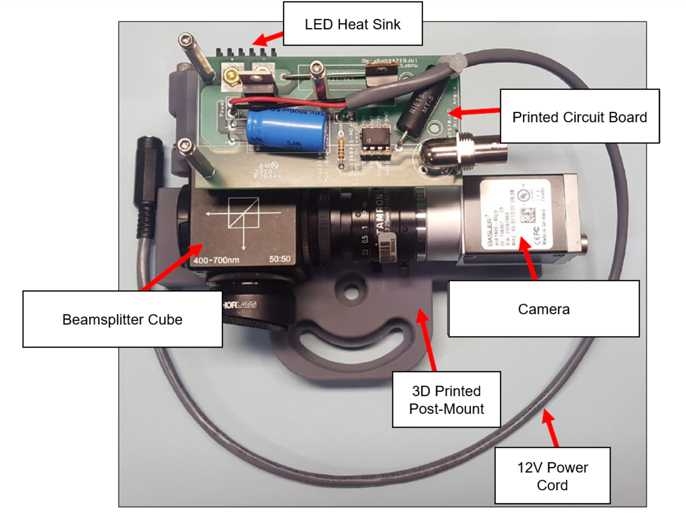
NASAs imaging system is comprised of a small CMOS camera fitted with a C-mount lens affixed to a 3D-printed mount. Light from the high-intensity LED is passed through a lens that both diffuses and collimates the LED output, and this light is coupled onto the cameras optical axis using a 50:50 beam-splitting prism.
Use of the collimating/diffusing lens to condition the LED output provides for an illumination source that is of similar diameter to the cameras imaging lens. This is the feature that reduces or eliminates shadows that would otherwise be projected onto the subject plane as a result of refractive index variations in the imaged volume. By coupling the light from the LED unit onto the cameras optical axis, reflections from windows which are often present in wind tunnel facilities to allow for direct views of a test section can be minimized or eliminated when the camera is placed at a small angle of incidence relative to the windows surface. This effect is demonstrated in the image on the bottom left of the page.
Eight imaging systems were fabricated and used for capturing background oriented schlieren (BOS) measurements of flow from a heat gun in the 11-by-11-foot test section of the NASA Ames Unitary Plan Wind Tunnel (see test setup on right). Two additional camera systems (not pictured) captured photogrammetry measurements.
instrumentation

Assembly for Simplified Hi-Res Flow Visualization
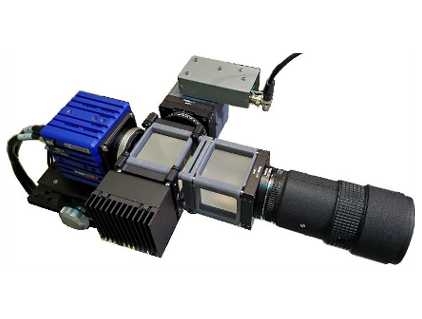
NASAs single grid, self-aligned focusing schlieren optical assembly is attached to a commercial-off-the-shelf camera. It directs light from the light source through a condenser lens and linear polarizer towards a polarizing beam-splitter where the linear, vertically-polarized component of light is reflected onto the optical axis of the instrument. The light passes through a Ronchi ruling grid, a polarizing prism, and a quarter-wave plate prior to projection from the assembly as right-circularly polarized light. The grid-patterned light (having passed through the Ronchi grid) is directed past the density object onto a retroreflective background that serves as the source grid. Upon reflection off the retroreflective background, the polarization state of light is mirrored. It passes the density object a second time and is then reimaged by the system. Upon encountering the polarizing prism the second time, the light is refracted resulting in a slight offset. This refracted light passes through the Ronchi ruling grid, now serving as the cutoff grid, for a second time before being imaged by the camera.
Both small- and large-scale experimental set ups have been evaluated and shown to be capable of fields-of-view of 10 and 300 millimeters respectively. Observed depths of field were found to be comparable to existing systems. Light sources, polarizing prisms, retroreflective materials and lenses can be customized to suit a particular experiment. For example, with a high speed camera and laser light source, the system has collected flow images at a rate of 1MHz.
Robotics Automation and Control

Robotic System for Infra-structure Reconnaissance
The robotic system is comprised of six main components: the orb that performs the reconnaissance, an orb injector housing that attaches to a piping network, a tether and reel subsystem that attaches to the back of the injector housing, a fluid injection subsystem that attaches toward the front of the injector housing, an external power and data subsystem, and associated control and monitoring software.
Usage of the system begins with an operator attaching the injector housing, with the orb stowed inside, to a flanged gate valve belonging to the piping network of concern. Requisite power, data, and fluid subsystems are attached, and the system is energized for usage. The orb is released via the tether and reel, and a controlled fluid force is imparted on the orb to help guide it along its mission. The tether supplies power and guidance to the orb, and relays real-time data back to the operator.
The orb’s interior features a modular plug-and-play architecture which may comprise COTS instrumentation for reconnaissance or investiga-tion, LIDAR, and inertial measuring and motion sensors. This instru-mentation could be used in combination with other sub-systems such as lighting, and core and sample retrieving mechanisms. These com-ponents are supported by other onboard devices such as a CPU, power source and controller, and data transmission encoders and multiplexers.
The Robotic System for Infrastructure Reconnaissance is at TRL 8 (actual system completed and "flight qualified" through test and demonstration), and is now available for licensing. Please note that NASA does not manufacture products itself for commercial sale.


